Introduction to OSI Models
A deep dive into the OSI (Open Systems Interconnection) model.
OSI Model (Open Systems Interconnection Model)
The OSI (Open Systems Interconnection) Model is a set of rules that explains how different computer systems communicate over a network. It was developed by the International Organization for Standardization (ISO).
The OSI Model consists of 7 layers, each with specific functions and responsibilities. This layered approach makes it easier for different devices and technologies to work together. It provides a clear structure for data transmission and helps in managing network issues. The OSI Model is widely used as a reference to understand how network systems function.
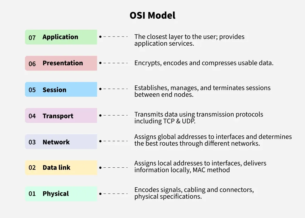
Layers of the OSI Model
There are 7 layers in the OSI Model, and each layer has its specific role in handling data:
- Physical Layer
- Data Link Layer
- Network Layer
- Transport Layer
- Session Layer
- Presentation Layer
- Application Layer
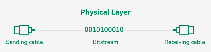
Layer 1 – Physical Layer
- The lowest layer of the OSI reference model.
- Responsible for the actual physical connection between devices.
- Handles data in the form of bits (0s and 1s).
- Responsible for transmitting individual bits from one node to another.
- On receiving data, it converts signals into bits and sends them to the Data Link Layer, which reassembles the frame.
- Common devices: Hub, Repeater, Modem, Cables.
OSI Model – Layer-Wise Explanation
The OSI (Open Systems Interconnection) Model is a conceptual framework developed by ISO that standardizes the functions of a telecommunication or computing system into 7 distinct layers. Each layer performs a specific role in the data transmission process.
Layer 1 – Physical Layer
The Physical Layer is responsible for the actual physical connection between devices. It handles raw data in the form of bits and transmits them over a physical medium. Learn more in the Physical Layer section.
Functions of the Physical Layer:
- Bit Transmission: Transmits individual bits from one node to the next.
- Bit Synchronization: Provides a clock to sync bit transmission between sender and receiver.
- Bit Rate Control: Determines the number of bits sent per second.
- Physical Topologies: Defines network arrangement (Bus, Star, Mesh, etc.).
- Transmission Mode: Supports Simplex, Half-Duplex, and Full Duplex modes.
- Physical Encoding: Converts bits into signals for transmission.
Devices: Hubs, Repeaters, Modems, Cables, Network Interface Cards (NICs), Transceivers
Layer 2 – Data Link Layer (DLL)
The Data Link Layer ensures error-free delivery of data from one node to another. Data at this layer is known as a Frame.
Sub-layers:
- LLC (Logical Link Control)
- MAC (Media Access Control)
Functions of the Data Link Layer:
- Framing: Encapsulates data into frames.
- Physical Addressing: Adds MAC addresses to the frame.
- Error Control: Detects and retransmits lost/damaged frames.
- Flow Control: Maintains consistent data rate.
- Access Control: Determines which device can access the channel.
Devices: Switches, Bridges
Layer 3 – Network Layer
The Network Layer ensures data transfer between different networks and handles routing and addressing. The unit of data is a Packet. Learn more in the Network Layer section.
Functions of the Network Layer:
- Routing: Selects the shortest/best path for packet delivery.
- Logical Addressing: Adds source and destination IP addresses.
- Address Resolution: Maps logical addresses to physical addresses using protocols like ARP.
Devices: Routers, Layer-3 Switches
Layer 4 – Transport Layer
The Transport Layer ensures complete and reliable end-to-end delivery of data. Data here is referred to as Segments. Learn more in the Transport Layer section.
Functions of the Transport Layer:
- Segmentation and Reassembly: Breaks data into segments; reassembles at receiver.
- Service Point Addressing: Uses port numbers to identify services/processes.
- Process-to-Process Communication: Enables communication between specific applications.
- Congestion Control: Prevents network overload.
- Quality of Service: Ensures appropriate service levels for different applications.
Services:
Protocols: TCP, UDP, SCTP, NetBIOS, PPTP
Layer 5 – Session Layer
The Session Layer manages sessions between two communicating devices. It sets up, manages, and terminates communication sessions. Learn more in the Session Layer section.
Functions of the Session Layer:
- Session Establishment, Maintenance, and Termination: Creates, manages, and ends communication sessions.
- Synchronization: Adds checkpoints to manage data recovery.
- Dialog Control: Supports half-duplex or full-duplex communication.
- Token Management: Controls access to shared resources in some protocols.
Protocols: NetBIOS, PPTP, RPC, SIP
Example Flow
A user sends a message through a Messenger app in their browser:
- The Application Layer provides the interface.
- The message is compressed and optionally encrypted.
- Data is then converted into bits to be sent across layers.
Each layer processes and adds its own header/trailer before sending it to the next layer below, following the OSI model.

Layer 6 – Presentation Layer
Also known as the Translation Layer. It prepares data from the Application layer for transmission over the network. Learn more in the Presentation Layer section.
Protocols Used:
- JPEG, PNG, GIF (Image formats)
- MPEG, MP3, MP4 (Media formats)
- TLS/SSL (Security protocols)
- ASCII, EBCDIC, Unicode (Character encodings)
Functions of the Presentation Layer:
- Data Translation: Converts data between different formats (e.g., ASCII to EBCDIC).
- Data Formatting: Ensures data can be read by the receiving application.
- Encryption/Decryption: Provides security by encrypting and decrypting data.
- Compression/Decompression: Reduces the number of bits transmitted.
- Character Code Conversion: Translates between different character encoding systems.
Layer 7 – Application Layer
Topmost layer in the OSI model. Interfaces directly with the end-user and applications.
Protocols Used:
- SMTP
- FTP
- DNS
- HTTP/HTTPS
Functions of the Application Layer:
- Network Virtual Terminal (NVT): Allows remote login to host.
- File Transfer Access and Management (FTAM): Enables file access, retrieval, and management.
- Mail Services: Provides email functionality.
- Directory Services: Offers global access to distributed databases.
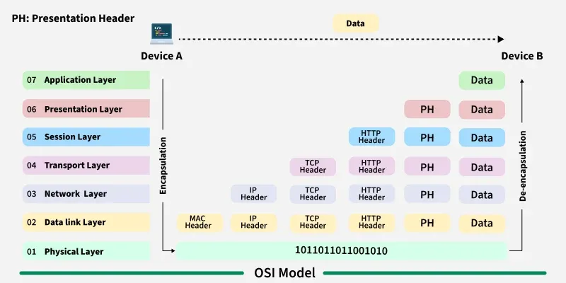
How Data Flows in the OSI Model
When data is transmitted between two devices, it travels through all 7 layers from sender to receiver:
Sender Side (Top to Bottom):
- Application Layer: Creates data.
- Presentation Layer: Formats/encrypts data.
- Session Layer: Establishes connection.
- Transport Layer: Segments data with error checking.
- Network Layer: Adds logical addressing and routes packets.
- Data Link Layer: Frames data with MAC address and error detection.
- Physical Layer: Converts frames into electrical/optical signals.
Receiver Side (Bottom to Top):
- Physical Layer: Receives signals.
- Data Link Layer: Extracts frames, verifies MAC and errors.
- Network Layer: Routes and reassembles packets.
- Transport Layer: Reorders and checks data segments.
- Session Layer: Manages connection session.
- Presentation Layer: Decrypts and formats data.
- Application Layer: Displays information to user.
Example: Sending an Email from Person A to Person B
- Application Layer: Person A uses Gmail/Outlook to write email.
- Presentation Layer: Mail is encrypted/formatted.
- Session Layer: A session is established over the internet.
- Transport Layer: Email split into segments with sequence numbers and error-checking.
- Network Layer: Determines best route and adds IP addresses.
- Data Link Layer: Adds MAC address, converts to frames, checks for errors.
- Physical Layer: Frames sent as electrical/optical signals via cables or WiFi.
At Person B's end: The process reverses and the email is displayed in their email client.
Protocols Used in the OSI Layers
| Layer | Working | Protocol Data Unit | Protocols |
|---|---|---|---|
| 1 – Physical Layer | Establishing physical connections between devices | Bits | USB, SONET/SDH, Ethernet (physical aspects), etc. |
| 2 – Data Link Layer | Node to node delivery of message | Frames | Ethernet, PPP, etc. |
| 3 – Network Layer | Transmission of data from one host to another across different networks | Packets | IP, ICMP, IGMP, OSPF, ARP, RARP, BOOTP, etc. |
| 4 – Transport Layer | Takes service from Network Layer and provides it to the Application Layer | Segments (TCP) / Datagrams (UDP) | TCP, UDP, SCTP, etc. |
| 5 – Session Layer | Establishes connection, maintains sessions, ensures authentication and security | Data | NetBIOS, RPC, PPTP, SIP, etc. |
| 6 – Presentation Layer | Translates and formats data from Application Layer for transmission | Data | TLS/SSL, MIME, JPEG, PNG, ASCII, EBCDIC, Unicode, etc. |
| 7 – Application Layer | Identifies client and synchronizes communication | Data | FTP, SMTP, DNS, DHCP, etc. |
Why Does the OSI Model Matter?
- Provides a clear structure of how data moves through a network.
- Helps in troubleshooting by isolating network issues to specific layers.
- While modern networks often use the TCP/IP model, OSI is still valuable as a learning and diagnostic framework.
- Simplifies understanding of complex networking concepts.
Difference Between OSI and TCP/IP Model
| OSI Model | TCP/IP Model |
|---|---|
| Stands for Open Systems Interconnection | Stands for Transmission Control Protocol/Internet Protocol |
| Has 7 layers | Has 4 layers |
| Guaranteed package delivery | Package delivery is not guaranteed |
| Only layers 1, 2, 3 are needed for transmission | All layers are necessary for transmission |
| Independent layers | Integrated layers |
| Mostly theoretical and conceptual | Widely used in practical networks |
| Example: Ethernet (Layer 2), IP (Layer 3) | Used in the Internet and most communication systems |
Advantages of OSI Model
- Breaks communication into 7 manageable layers.
- Makes troubleshooting easier by isolating problems.
- Provides standardization across network components.
- Flexible for updates, as each layer can evolve independently.
Disadvantages of OSI Model
- Too complex for beginners.
- Not widely implemented in its pure form in real-life networks.
- Layer-by-layer processing can be time-consuming.
- Acts more as a conceptual guide than a practical model.
Conclusion
The OSI (Open Systems Interconnection) Model is a conceptual framework that defines how data moves across a network using 7 distinct layers. While the TCP/IP model is more practical and widely adopted, OSI still plays a crucial role in teaching, designing, and troubleshooting networks. Understanding the OSI model equips users with the foundational knowledge needed to work with modern networking technologies.
Test Your Knowledge
Take a quiz to reinforce what you've learned
Exam Preparation
Access short and long answer questions for written exams